

#Servo motor projects pro#
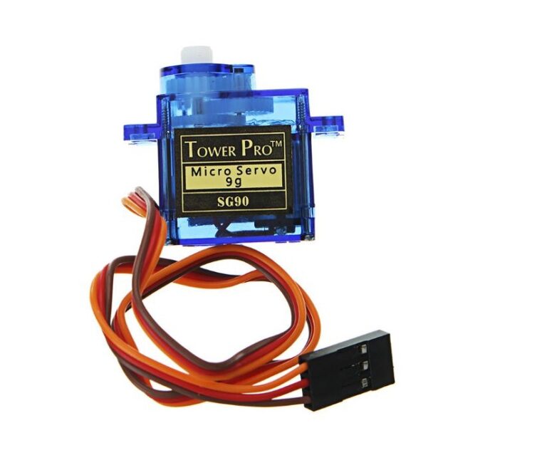
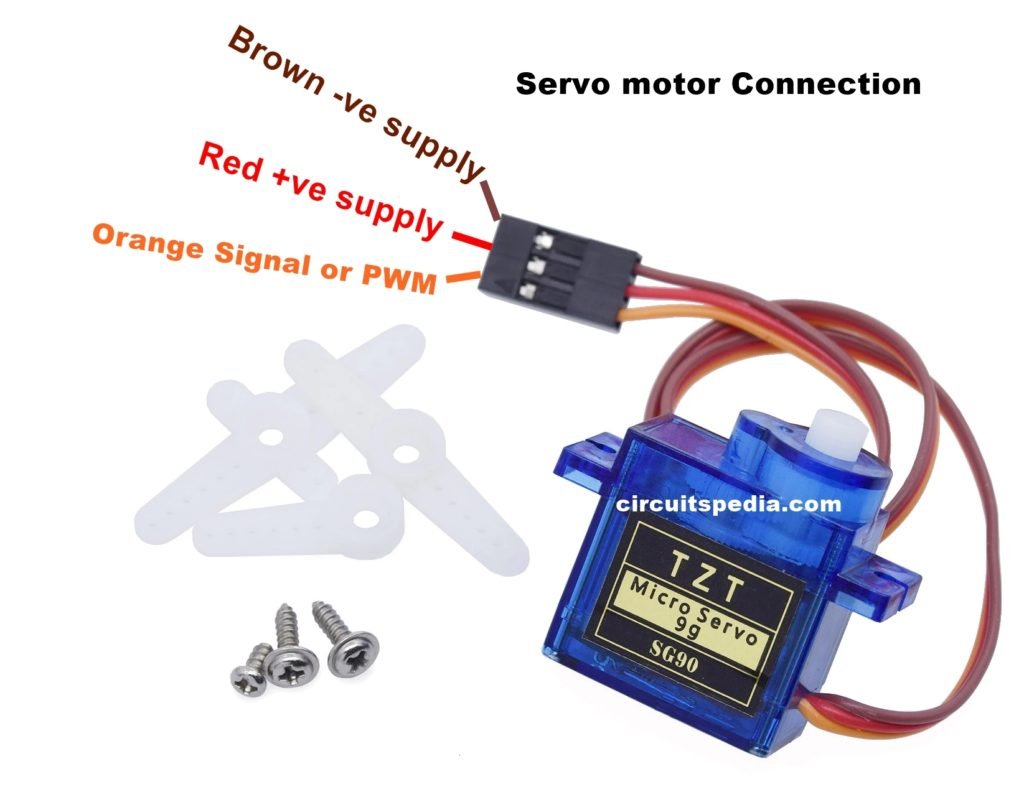
The servo motor used in this project is Tower Pro SG90. As per the feedback from the position sensing system (like a potentiometer), when the servo achieves the desired position, the power to the motor is terminated.Įven though the power supply to the motor inside the servo motor is not constant, the overall power should be constant as the servo motor has a dedicated system that controls the power. The DC Motor in the servo motor is powered as per the control signal it receiver. But rather, it is used to determine the position of the servo meter. The control signal is usually a PWM signal but this PWM signal is not used to control the speed of the motor as in case of a DC Motor. Here, the control signal will determine the position of the servo motor’s shaft. The Red wire is used for supply, the Brown wire is used for ground and the Orange wire is used for control signal. These are usually color coded as Red, Brown and Orange (may vary with different models). Typically, simple servo motors consists of three wires. Servo motors are available as both AC Servo motors and DC Servomotor with each type having its own areas of applications.Ī simple servo motor (as the one used in this project) consists of a small DC motor, a potentiometer for providing position feedback, a gear system for increased torque and a control system. Its features like Analog to Digital Converter (ADC) and Pulse Width Modulation (PWM) are used in this project.Īs mentioned in the introduction, a servo motor is a type of DC motor which is used for precision control. Hardware: ARDUINO UNO, power supply (5v), 100uF capacitor, buttons (two pieces), 1KΩ resistor (two pieces), Servo motor (which needed to be tested).The main processing module of the project is Arduino UNO board. 1ms of ON time and 17ms of OFF time in a 18ms signal.įor the shaft to be moved to 12o clock the ON time of signal must be 1.5ms and OFF time should be 16.5ms. This ratio is decoded by control system in servo and it adjusts the position based on it. This PWM in here is generated by using ARDUINO UNO. Based on this DUTY RATION the control electronics adjust the shaft.Īs shown in figure below, for the shaft to be moved to 9o clock the TURN ON RATION must be 1/18.ie.

The important thing here is the DUTY RATIO of the PWM signal. The frequency of PWM (Pulse Width Modulated) signal can vary based on type of servo motor. This data regarding position of shaft is sent through the SIGNAL pin. The position data to the control should be sent in the form of PWM signal through the Signal pin of servo motor. Simply speaking the control electronics adjust shaft position by controlling DC motor. Arduino Tutorial Online Courses Video Training.
#Servo motor projects pdf#
Arduino Nano Projects List in PDF offline downloadable.
#Servo motor projects android#
Android based arduino Projects List Download PDF.esp8266 arduino projects list in pdf offline downloadable.Arduino Proteus Projects List for Download.Arduino UNO Projects List in PDF offline downloadable.Arduino Mega 2560 projects list in PDF offline downloadable.Arduino Complete Projects List PDF Downloadable.Huge List of tutorials & Components based resources.


 0 kommentar(er)
